SMD – DIGESTER

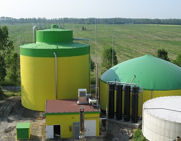
SMD is a patented digester (up to 2.400m³ volume) with two upright cylindrical tanks, one inside the other, without mixers. The only moving part is a gas valve situated in a wide gas pipe connecting the two chambers. The efficient agitation process in the SMD is achieved by mixing intervals based on the formation of biogas and a pressure-controlled function of the gas valve.

Conventional biogas plants work with different types of agitators in the fermenting chambers; they require additional electricity and must be maintained regularly.

SMD – SELF MIXING DIGESTER

In the SMD, there are no mixers! Therefore: “There are no moving parts, thus nothing can break”.

SMD – A four stage process

Balanced state

In its balanced state, the gas valve, situated in a wide gas pipe connecting the main and secondary fermenter chambers, is open. This allows a balance in the fluid level between the two chambers.

Compressing period

In the compressing period, the gas valve is closed. Biogas produced in the outer fermenter chamber can not escape, presses the liquid level. The displaced substrate moves into the secondary fermenter chamber via the four to eight static mixer jets situated at the bottom of the SMD.

  • approximately 110m³ of fermented substrate are pressed into the inner chamber
  • The pressure difference between the fermenter chambers is up to 450mbar
  • The fluid levels in the main and secondary chambers vary approx. 4,5 meters

Resting period

When the preset pressure difference (450mbar) between the main and secondary fermenter chamber is reached, the so called “resting period” starts. This means that the digested substrate (also called effluent or digestate)  drains into  the follow up fermenter or storage tank / lagoon.

Mixing period

The mixing phase begins at the end of the resting period, by a sudden opening of the gas valve. Within a fraction of second, it reaches pressure equilibrium. A huge crater is formed on the surface of the ferment in the secondary chamber. This destroys the floating layer. In the following five to ten seconds, the ferment is flushed out of the secondary fermenter chamber into the main fermenter chamber. The substrate  flows in three different directions, at the same time.

Substrate flow through short mixer columns: Under high pressure, digested material with a high proportion of starved bacteria is sprayed into the fresh, undigested material in the main fermenter chamber, via the short mixer columns.

Substrate flow through static mixer jets: At the same time, material is forced into the main fermenter chamber by the static mixer jets. The digested material is re-worked into the active ferment (approx. 50 – 75 m³ in five seconds via four to eight nozzles). Due to the high amount of energy released, the fluid column in the main chamber starts to rotate. This rotation facilitates the spraying of every square centimetre of the upper surface in the main fermenter chamber with the substrate from the secondary fermenter chamber via the short and long mixer columns. The floating layer is destroyed and re-worked into the ferment.

Substrate flow through long mixer columns: In the ground sludge layers of a biogas unit, there is a high concentration of starved bacteria, due to the insufficient nutrient supply. Part of this material is worked back into the top of the biomass via the long mixer columns and mixed into the undigested material in the main chamber. The surplus supply of nutrients causes a rapid multiplication of the quantity of bacteria. The production of biogas can  achieve a maximum in a very short period of time.

Time duration from one mixing interval to the next depends on the input materials. Usually, it varies between one and two hours, depending on the digestibility of the substrate. Input material with high energy generates shorter mixing intervals.

DETAILS AND ADVANTAGES OF THE SMD

Plug flow procedure / Preset substrate flow

It is possible to achieve a high biogas yield with the SMD in a shorter period of time due to the “preset substrate flow”. The injected substrate follows specific paths through the SMD; no shortcuts are possible.

  • Fresh input material is deposited onto the upper surface in the main fermenter chamber and worked into ferment by the mixing process.
  • Laws of nature state that lighter material rises to the top; the biomass sinks to the bottom of the fermenter chamber only after it has been digested to a certain degree.
  • Different materials demonstrate different characteristics in the time needed for this process, and in the SMD, the available potential can be used more effectively. The substrate slowly falls  to the bottom of the main fermenter chamber and is then forced through the static mixer jets. The substrate then moves slowly upwards into the secondary fermenter chamber, and the effluent can be drained off when reaching the highest point.

A considerable advantage of the “preset substrate flow” is that methane bacteria with a relatively slow growth rate are not flushed out of the fermenter. Instead, they are kept within the digester, and the high density of bacteria groups leads to fast digestion.

No mixers in the digester!

The aim of a biogas plant is an efficient production and extraction of biogas. Since biogas will be produced throughout the digester and must rise upward toward the top of the fermenter chamber, conventional units require the use of mixers. The SMD uses a different operation system to overcome this necessity; like carbon dioxide in a shaken bottle of fizzy water, in the SMD the biogas is set free and rises  to the top by itself through the periodic compression and expansion of the substrate.

Conventional mixer units create shear forces within the ferment. These forces destroy a large portion of the flakes, which have formed clusters of different bacterial strains. The highly sensitive equilibrium state of these bacteria, which aids in gas production, will be destroyed and, therefore, reduce efficiency. However, this is not the case for the SMD; as soon as the ferment leaves the upper stress zone of the main fermenter chamber, there are no more shear forces. The nutritional requirements and, thus, the life function of the flakes, are secured by the transportation of dissolved matter and ions within the watery solution.

The constant compression and expansion of the ferment allows cavities to form, through which nutrients can reach the bacteria. The flakes are able to grow without interruption, and very high process stability can be achieved.

Constant Temperature in the fermenter

An important factor to gain a high yield of biogas is constant temperature. Just as important is the gentile heating of the liquid manure. In the SMD, the constant temperature is maintained with approximately 8.000m of integrated wall and floor heating. With such a large surface area, it is possible to have a low supply temperature. Through gentile warming of the substrate, the bacterial strains can develop in the material and, thus, increase the biological effect of the system.

Other biogas plants with external heat exchangers must be heated to above their optimal temperature for efficient digestion. Therefore, the heat losses of the unit must be balanced. If additional heating is required, active ferment must be pumped through the heat exchangers. Only very few bacteria can survive such a dramatic rise in temperature and, consequently, the whole process, –from hydrolysis to methane production– must restart from zero.

In some other digesters, the heat exchangers are fixed to the wall. Thus, the digester might show a poor heat transfer, due to the fact that thin surfaces require high temperatures to stay warm. High temperatures destroy the bacteria. The heating pipe becomes overgrown with fibrous matter, which reduces heat transmission and efficiency; therefore, heat the transfer process becomes worse over time. The chamber must then be emptied and the heating pipe cleaned. A loss of earnings is guaranteed.

Extraction of ground sludge

Due to the fermenting process, the sediments fall to the bottom. Over the years, the sediments layers grow, decreasing the volume of the digester, thereby decreasing the biogas production. Consequently, the operator of the biogas plant must stop to remove the sediments.

Thanks to the sludge drain in the SMD, the extraction of ground sludge and grit can be done without stopping fermentation. This enables the SMD to work with complicated feedstock, such as poultry slurry, despite the fact that it normally has a high percentage of sand and grit.

SMD Referenz 1
SMD – SELF MIXING DIGESTER

EXAMPLE PLANT

Preliminary tank:

  •  450 m³ volume

 Fermenter:

 Self Mixing Digester (SMD)

  • No mixers/ no technology in the fermenter
  • Cement construction with sprayed on insulating foam
  • Integrated wall
  • And underfloor heating
  • 2,400 m³ volume

Secondary fermenter:

  • Cement construction with isolation and foil roof
  • 2,500 m³ volume
  • Extern biological desulfurization

 BHKW:

  • 537 kW el. 617 kW therm.
  • Local heat network with greenhouse

Input substrates:

  • Cattle slurry and pig manure, renewable resources

Commissioning:

2006

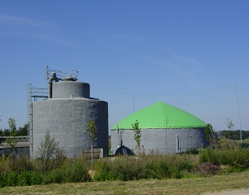
SMD Referenz 2
SMD – SELF MIXING DIGESTER

EXAMPLE PLANT

Preliminary tank:

  • 300 m³ volume

Fermenter:

Self Mixing Digester (SMD),

  • No mixers/ no technology in the fermenter
  • Cement construction with sprayed on insulating foam
  • Integrated wall
  • And underfloor heating
  • 1,800 m³ volume

Secondary fermenter:

  • Cement construction with isolation and foil roof
  • Integrated wall heating
  • integrated desulfurization

BHKW:

  • 469 kW el.
  • 539 kW therm.

Substrates:

  • Cattle slurry, renewable resources, grass silage

Commissioning:

2003

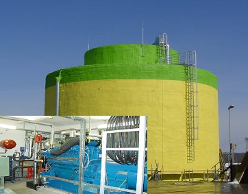
SMD Referenz
SMD – SELF MIXING DIGESTER

EXAMPLE PLANT

Preliminary tank:

  • 400 m³ volume

Fermenter:

Self Mixing Digester (SMD),

  • No mixers/ no technology in the fermenter
  • Cement construction with sprayed on insulating foam
  • Integrated wall
  • And underfloor heating
  • 2,400 m³ volume

Secondary fermenter:

  • Cement construction with isolation and foil roof
  • Integrated wall heating
  • integrated desulfurization
  • 2,500 m³ volume

BHKW:

  • 537 kW el. 617 kW therm.

Substrates:

  • Cattle slurry, renewable resources

Commissioning:

2007